Chapter 6
Idlers
One of our early readers, Brian Wood, raises a valid query about what's written on page 73, where I have said "If more than one idler is used, they should all have the same number of teeth".
With hindsight, my choice of "should" is unintentionally misleading, so a bit of clarification is required.
First of all, it might have been clearer if I had written "Here's a recommendation which always works: If more than one idler is used, they should all have the same number of teeth". I did not intend to imply they "must" have the same number of teeth, as that would not be true; simply that the easiest way to deal with multiple idlers, without delving into more complex explanations at that point, is to use idlers with the same numbers of teeth.
Bearing in mind that on page 73 we are discussing simple non-compound gears which have one gear on each axle (known as co-planar gears), and not compound gears (pages 74 onwards):
Let's be clear; idlers can have any number of teeth, and where there is more than one idler, they do not all have to have the same number of teeth. It is easier to understand what's happening if they do all have the same number of teeth, but they can all have different numbers of teeth if that makes it easier to physically mount and mesh the idlers between the fixed spindle and leadscrew gears.
Let's think a little more about idlers.
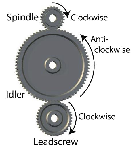
A single idler can be used to change the direction of rotation of a following gear. Fig 6.14 (page 73) is reproduced on the right, and shows how one intermediate gear (idler) changes the direction of rotation of the following gear (the Leadscrew gear, if the spindle is driving the train). Fig 6.15 (page 73) shows that the position of the idler can be arranged to suit the fixed centres of the spindle and leadscrew gears. In the real world, that only works if the size and position of the idler can be adjusted so that it meshes properly with both gears, and that's why idlers are often mounted on sliding arms (shown in fig 6.16 at the bottom of page 73). The size of the i
odler depends on the number of teeth, so it is fortunate that the number of teeth in the idler makes no difference to the overall gear ratio between the spindle gear and the leadscrew gear. Mathematically, the number of teeth on the idler cancel out.
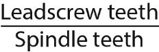
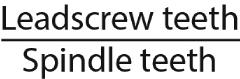
Pages 70 and 71 explain gear ratios, so, taking the gear ratio between two gears as
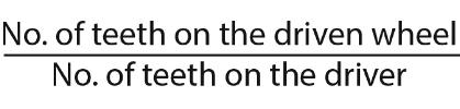
With no idler, that's the
Adding an idler means we now have a ratio between spindle and idler, and a second ration between idler and leadscrew. The overall ratio is found by multiplying these two individual ratios:
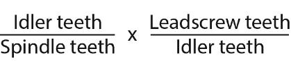
Writing these as fractions, and using the rules shown in the RATIOS box on page 71 means we have can cancel the idler teeth which appear on the top and bottom of the fractions, resulting in the overall ratio of
which does not depend on the idler at all. Having the idler in the train does still change the direction of rotation of the leadscrew gear compared to a train which does not have the idler, but doesn't affect the overall ratio.
Adding another idler also has no effect on the overall gear ratio.
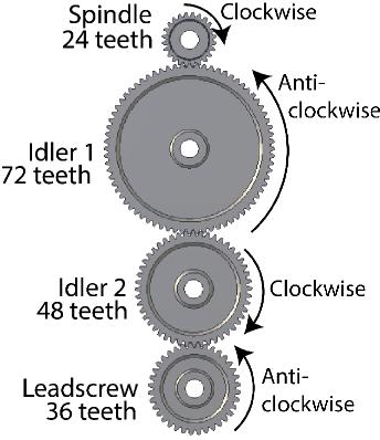
Fig 6.14B (opposite) shows a train with two idlers. If we call the first idler Idler 1 and the second Idler 2, the overall gear ratio is:
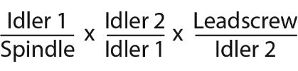
Cancelling identical terms top and bottom, we have an overall ratio of
which does not depend on the number of teeth in any of the idlers.
Idler 1 always appears on the top and the bottom of the fractions, and can be cancelled out, and so does Idler 2, so not only do the idlers have no effect on the overall ratio, the number of teeth on each idler has no effect on the other idler.
Why use more than one idler?
If one idler changes the relative direction of rotation of the following gear, adding an additional idler reverses that direction again (see fig 6.14B - opposite). In practice, with no idlers, the leadscrew rotates in the opposite direction to the spindle. Adding one idler (intermediate gear) between spindle gear and leadscrew gear reverses the direction of the leadscrew, so that the leadscrew rotates in the same direction as the spindle. Addin more idlers adds more reversals. As a rule of thumb, where we have a spindle gear and a leadscrew gear, adding an odd number of idlers makes the leadscrew rotate in the same direction as the spindle. Adding an even number of idlers makes the leadscrew rotate in the opposite direction to the spindle.
Within the constraint of direction, having the freedom to choose the number of idlers and the freedom to choose idlers without having to worry about the number of teeth on any idler means there is considerable flexibility in the physical layout of the gears in the train, to suit the centres of the spindle and leadscrew, and the gears available for a particular lathe.
I hope that helps. It's a more long-winded explanation than "should", but my intention was not to dwell on idlers on page 73, but to move swiftly on to the more important explanation of compound gears, on page 74 of the book. There was also the practical constraint that the chapter had to end at the bottom of page 77, so there was a degree of pruning and selection in what could have been a very long chapter indeed. The minutiae of gear ratios for screwcutting is interesting, of course, and might deserve a book on its own.
Fig 6.14 (Book : Page 73)
Fig 6.14B (not in the book)
Example:
In fig 6.14B, if the train had no idlers and simply consisted of the spindle gear and the leadscrew gear, meshed together, the overall gear ratio would be:
36 / 24 = 3 / 2 or 1 : 2/3
so for every one turn of the spindle, the leadscrew makes 2/3 of a turn. TWith no idlers, the leadscrew turns in the opposite direction to the spindle.
Adding one idler (Idler 1, with 72 teeth) gives an overall ratio of:
72 / 24 x 36 / 72 = 36 / 24 = 3 / 2 or 1 : 2/3 (same as above)
showing that the single idler has no effect on the overall gear ratio. With one idler, the spindle and leadscrew gears turn in the same direction.
Adding the second idler (Idler 2, with 48 teeth) gives an overall ratio of:
72 / 24 x 48 / 72 x 36 / 48 = 36 / 24 = 3 / 2 or 1 : 2/3 (same as above), showing that two idlers has no effect on the overall gear ratio. In this case, with two idlers, the leadscrew turns in the opposite direction to the spindle.
© Copyright Marcus Bowman 2015 et seq | All Rights Reserved